Basic HTML Version


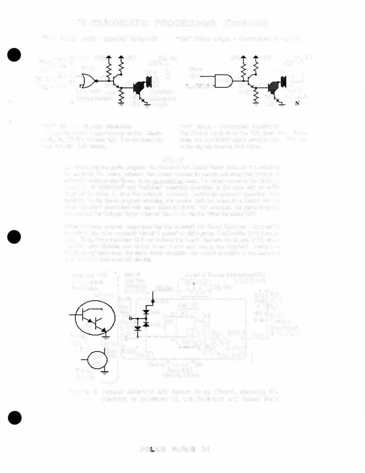
"On" State Logic ~ Con trol led Solenoid
TEST/DIAGNOSTIC PROCEDURES
(Continued)
"On" State Logic· Specia l Solenoid
•
From 7407
PIA
Spl
Sol.
..n.:
Trigger
1J1
a
I .
2N
Low,
With
4401
flippers enabled
Sol.
B+
+2:.5VV~.
lJ1BJ.-?
Special
Solenoid
"ON"
•
•
"Off" State •
Spec ial
So leno id:
The Special Switch Trigger Input goes low. Mean-
while. the PIA line remains high. The remaining sig-
nals reverse their states.
+5V
Sol. B+
+25V
S
1J19
BJ---}
Cntrld
"ON"
"Of f" State - Control led So lenoid :
The Enable Input (from the PIA) goes low. Mean-
while, the BLANKING signal remains high. The rest
01the signals reverse their stales.
NOTE
As directed by the game program, the Solenoid Ale Select Relay (solenoid 12) switches
the solenoid B+ power between two power busses to permit actuating two groups of
solenoids at the proper limes. In its de-energized state. Ihe Relay connects the 'circuit A
power' to 16 ·controlled- and -switched- solenoids (identili.ed in the table with no suffix
letter or the letter A, after the solenoid number). Individual solenoid operation then
depends on the game program enabling the ground path for solenoid actuation via the
driver transistor associated with ea.chsolenoid circuit. For example ..the game program
can actuate the Outhole Kicker solenoid (sol. alA), via the driver transistor 033.
When the game program determines that the Solenoid
AlC
Select Relay (sol. 12) must be
energized, the relay connects 'circuit C power' to eight group C solenoids (01C through
aBC). Now. driver transistor 033 can actuate the Shark Flashers circuit (sol. OIC), which
has Iwo lamp circuits. one to the Insert Board and one to the playfield. Using this
"multiplexing- technique, the same driver transistor can control actuation of two separate
(A side and C side) solenoid circuits.
•
•
,
SJ11-1i
Orn
Figure 4. Typical Sole noid AIC Select Re lay Circuit, .show ing the
function of Solenoid 12, the Soleno id
Ale
Select Relay_
•