Basic HTML Version


TEST/DIAGNOSTIC PROCEDURES
(Continued)
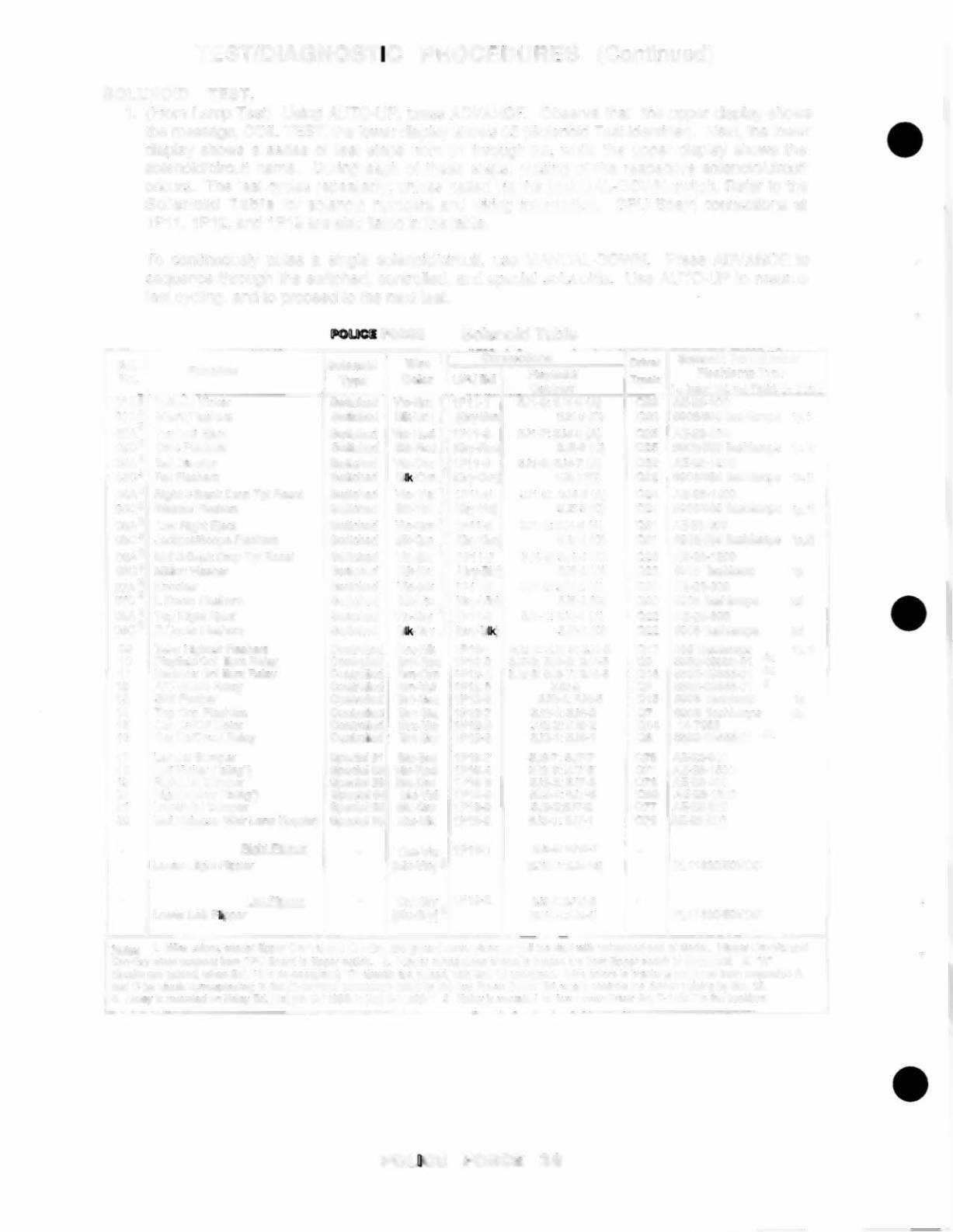
SOLENOID TEST.
1. (From Lamp Test) Using AUTO-UP, press ADVANCE. Observe that the upper display shows
the message, COIL TEST, the lower display shows 05 (Solenoid Test identifier). Next, the lower
display shows a series of test steps from 01 through 22, while the upper display shows the
solenoid/circuit name. During each of these steps, pulsing of the respective solenoid/circuit
occurs. The lest cycles repeatedly, unless hatted via the MANUAL-DOWN switch. Refer to the
Solenoid Table for solenoid numbers and wiring information. CPU Board connections at
1P11, 1P12, and 1P19 are also listed in the table.
To continuously pulse a single solenoid/circuit, use MANUAL-DOWN. Press ADVANCE to
sequence through the switched, controlled, and special solenoids. Use AUTO-UP to resume
test cycling, and to proceed to the next test.
Solenoid Table
Sol.
Solenoid
Wlr. 1
Connection,
Drtnr Solenoid Part Number
Function
Flashlemp Type
No.
Type
Color
CPUBd
Playfleldl
Tm.lr
Cabinet
•• InsertBel:p.prr,ald· d. Oomo
01A3 Oulhole Kickef
Switched Vio-Bm
J
1PH-1
5J1-9: 5J4-9 (A)
033 AE-23·800
01C 3 Shark Flashers
Switched Bk-Brn (Gry-Bm
5J5-9 (C)
033
#906f#89
flashlamps lp.1'
02A
3
Top len Ejecl
Swilched Via-Red}
lP11-3
5J1-7: 5J4-8 (Al
025 AE-23-800
02C 3 Croc Flashers
Switched BIk-Red (Ory-Red
5JS-S (C)
025 #906/#89 lIashlamps lp, Ii
03A 3 Ball Diverter
Switched Vio-Om}
lP11-4
5J1-6: SJ4-7 (AI
032 AE-2S-1200
03C3 Ral Flashers
Switched Blk-Om (Ory-Om
5JS-7(C)
032
M9061#89
lias hiamps lp.l;
04A 3 Righi 3-Bank Drop Tgi Reset
Switched Vio- Yel } lP11-5
5J1-5: SJ4-6 (Al
024 AE-2S-1200
04C3 Weasel Flashers
Switched BII-Yel
(Gr;-YeI)
5J5-5 (Cl
024 #906/#89 lIashlamps
tp.u
05A 3 lwr Righi Ejecl
Switched Vlo-Gm}
lPl'-S
5J1-4: SJ4-5 (AI
031 AE-23-800
05C 3 JackpoVScoptl Flashers
Switche<l
BII-Gm (Gry-Gm
SJ5-4 (C)
031 #906/#89 lIashlamps lp.2i
06A 3 Mdl3-8ank Drop Tgi Reset
Switched VIO-Blu } lPl1·7
5J1-3: SJ4-4 (A)
023 AE·26-1200
06C3 MilUonFlasher
Switctled Blk-Blu (Gry·BIu
SJ5-3 (C)
023 #906 lIashlamp
lp
07A 3 Knocker
Switched Vio-Blk}
1Pl1-8
5J1-2: 5J4-2 (AI
030 AE-23-800
07C 3 L Dome Flashers
Switched elk-VlO
(Gry-VIO)
SJ5-2 (C)
030 #906 Uashlamps
2d
08A 3 Top Right Ejecl
Swilched Vio-Gry } lPII-9
5Jl-l: 5J4-1 (A)
022 AE·23-800
08C 3 R Dome Flashers
Swilched 8Ik-G.ry (Ory-BIk)
SJS-l (Cl
Q22 #906 flashlamps
2d
09 Take Highest Flashers
Controlled Bm-Bk 1P12-1 5J2-9: 5J6-9: 2J4-3 017 #89 Uashlamps
lp,li
10 Playlield Gnl Ilium Relay
Conlrolled Bm-Red lP12·2 5J2-S: SJ6-8: 2J4-5 09 5580-09555-01 48
11 BacloboxGnilium Relay
Controlled Bm-Orn 1P12-4 5J2-6: 5J6-7: 2.14-6 016 5580-09555-01 48
12
AlC
Select Relay
Conlrolled Bm-Yel
lP12-5
5J2-5
08 5580-09555-01 5
13 Skill Flasher
ConlJoIled Bm-Gm lP12-6
5J2-4: 5J6-5
015 #906 flash lamp
lp
14 Top Cop Rashers
ConlJoiled Bm-Blu lP12-7
5J2-4: 5J6-3
07 M906 lIashlamps
2p
15 Car On/Oil Molor
ConlJoIled
Bm-Via
lP12-8
5J2-2: SJ6-2
014 14-7953
16
Car UpJDown R.elay
Controlled Bm-Gry lP12-9
5J2-1 : SJ6-1
06 5500-09555-01 4a
17 lell Jet Bumper
Special.,
Blu-Bm lPl9-7
5J3-7: SJ7·7
075 AE·23·800
18 leI! Kicil.er ("sling'
Special 12 Blu-Red 1PI9-4
5J3-6: 5J7-6
071 AE-26-1500
19 Righi Jel Bumper
Special~ Btu-Om lP11J.3
5J3-3: SJ7-3
073 AE-23·aOO
20 RighI Kicker ("sling,
Special ,~ 81u-Yel
lP11J.·8
5J3-4: 5J7-5
069 AE-26-1500
21 lower Jet Bumper
Special
IS
Blu-Gm lP1P-a
543-2:5J7-2
on
AE-23-800
22 Ball Release (Shlr lane Feeder) Spedall6 Blu-Slk lP11J.9
5J3-1 : 5J7-1
079 AE-23-800
-
RighI Flipper
-
Om-Via lPI9-1
2.15-5:2Jl0-7
-
Lower Righi Flipper
IBkI·Via1 2
(2Jl0·1: 2Je·15)
FlI1630/SOVDC
-
Leb Flipper
-
Om-Gry lPI9-2
2J5-4: 2J10-e
Lower Len FUpper
IBlu-GlY) 2
l2Jl()'2:2J8-4 )
FL
11630!50VOC
t-l.cJ.as.
1. Wi'e colors. e~capl HipperOmNia snd Om-City,arll groundconnections
(10
coil terminalwith unbElndedend
01
diode). FlipperOm-Vio and
Orn-Grywires connect lromCPU Board
kI
ftipperswildl. 2. Flipper connectionsshownin bracesare IromHipperswitch
10
Hippe'coil. 3. -A"
circuits a.e pulsed, when Sol. 12 is d_n8l"gized; ·C· cimlits 1118pulsed.with Sol. 12energized. Wi'e colors in bracketse'e Ihose 'rom respectiveA
and C tIiIrminal$corresponding
kllh
JHarminaJ connectionUstad!or
the
Aux Powe.
Drille.
Bd, which connols !he devica pulsing by Sol. 12.
4. Retay is mountedon Relay Bd. (4a) pin C·1199&-1;(4b) C·11902·1. 5. RMY is mounl8d on Aux PowerDriver Bd. 0·12247 in
tile
backoox.
•
•
•