Basic HTML Version


Sol.
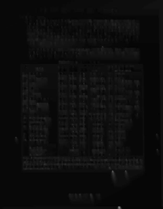
Solenoid
Wire 1
Connections
Driver Solenoid Part Number
Function
Playfield!
Flashlamp Type
No.
Type
Color
CPUBd
Trnatr
Cabinet
g= B'glass; p=PI'field
01A;'
Outhole Kicker
Switched Via-Bm } 1P1H 5J1-9: 5J4-9 (A)
033 AE-23-800
01C 3 Flash 1
Switched Blk-Bm (Gry-Bm)
5J5-9 (C)
033 #89/906 flash lamps 4p
02A 3 Shooter Lane Feeder
Switched Via-Red } 1P11-3 5J1-7: 5J4-8 (A)
025 AE-23-S00
02C3 Flash 2
Switched Blk-Red (Gry-Red)
5J5-S (C)
025
#891906
flashlamps 2p,1g
03A 3 Not Used
Switched Via-om}
1P11-4 5J1-6: 5J4-7 (A)
032
03C 3 Flash 3
Switched Blk-Om (Gry-Om)
5J5-7(C)
032 #89/906 flashlamps 1p,2g
04A 3 Ball Popper
Switched
VK>-
Yel} 1P11-5
5J1-5: 5J4-6 (A)
024 AE-24-900
04C3 Flash 4
Switched Blk-Yel
(Gry-YeI)
5J5-5 (C)
024 #S9/906 flashlamps 1p,2g
05A 3
Not Used
Switched Via-Gm}
1P11-6
5J1-4: 5J4-5 (A)
031
05C 3 Rash 5
Switched BIk-Gm (Gry-Gm)
5J5-4 (C)
031 #S9/906 flash lamps 2p,2g
06A 3 3-Bank Drop Target Reset
Switched Via-Blu } 1P11-7
5J1-3: 5J4-4 (A)
023 AE-26-1200
06C 3 Rash 6
Switched Blk-Blu (Gry-Blu)
5J5-3 (C)
023 #S9/906 flashlamps lp,2g
07A 3 Knocker (in Backbox)
Switched Via-Blk } 1P11-S 5J1-2: 5J4-2 (A)
030 AE-23-S00
07C 3 Rash 7
Switched Blk-Vio (Gry-VIO)
5J5-2(C)
030 #S91906 flash lamps lp,2g
08A 3 Lock Diverter
Switched VIO-Gry } 1P11-9
5J1-1: 5J4-1 (A)
022 AE-24-900
08C 3 Flash 8
Switched BIk-Gry (Gry-BIk)
5J5-1 (C)
022 #S9 flash lamps
3p
09 Flash 9
Controlled Bm-Blk 1P12-1 5J2-9: 5J6-9: 2J4-3 017 #89/906 ftashlam,fes lp,2g
10 Insert Bd Genllllum Relay
Controlled Bm-Red 1P12-2 5J2-S: 5J6-8: 2J4-5 Q9 5580-09555-01 a
11 Playlield Genllllum Relay
Controlled Bm-Om 1P12-4 5J2-6: 5J6-7: 2J4-6 016 5580-12145-00 4b
12 A!C Select Relay
Controlled Bm-Yel
1P12-5
5J2-5
as
5580-09555-01 5
13 Upper Kickback
Controlled Bm-Gm 1P12-6
5J2-4: 5J6-5
015 AE-23-BOO
14 Lock Kickback
Controlled Bm-Blu 1P12-7
5J2-3: 5J6-3
07 AE-23-BOO
15 Lell Kicker ("sling")
Controlled Bm-Vio 1P12-S
5J2-2: 5J6-2
014 AE-23-S00
16 Right Kicker ("sling")
Controlled Bm-Gry 1P12-9
5J2-1: 5J6-1
06 AE-23-BOO
17 Left Jet Bumper
Special #1 Blu-Brn 1P19-7
5J3-7: 5J7-7
075 AE-23-800
18 Ramp Diver1er
Special #2 Blu-Red 1P19-4
5J3-6: 5J7-6
071 AE-23-BOO
19 Right Jet Bumper
Special #3 Blu-Om 1P19-3
5J3-3: 5J7-3
073 AE-23-800
20 Outlane Kickback
Special #4 Blu-Yel
1P19-6
5J3-4: 5J7-5
069 AE-23-800
21 Lower Jet Bumper
Special #5 Blu-Gm 1P19-S
5J3-2:5J7-2
on
AE-23-BOO
22 Deep Freeze Magnet
Special #6 Blu-Blk 1P19-9
5J3-1: 5J7-1
079 8-13522
-
Righi Flipper
-
Om-Vio 1P19-1
2J5-5: 2J10-7
-
Lower Right Flipper
[Blu-VIO) 2
[2Jl0-1: 2J8-l5]
FL11630/50VDC
Upper Right Flipper
[Blu-Yeq 2
[2Jl0-3: 2J8-13]
FL11630/50VDC
-
Left Ripper
Om-Gry 1P19-2
2J5-4: 2J10-8
Lower Left Ripper
-
[B1u-Gry) 2
[2J1O-2:2J8-14]
-
FL11630/50VDC
Notes:
1. Wire colors, except flipper Om-Vio and Om-Gry, are groundconnections(to coil terminalwith unbandedend of diode). FlipperOrn-Vioand
Om-Grywires connect fromCPU Board
1D
flipper switch. 2. Flipperconnectionsshown in bracesare fromflipper switch
1D
flipper coil. 3. "A" circuitsare
pulsed,when Sol. 12 is de-energized;
-co
circuitsare pulsed,with Sol. 12 energized. Wire colors in bracketsare those from respectiveA and C terminals
correspondingto the J1-terminalconnection listedfor the Aux PowerDriver Bd, which controlsthe devicepulsingby Sol. 12. 4. Relay is mountedon
Relay Bd, (4a) pin C-11998-1;(4b)C-11902-1. 5. Relay is mountedon Aux Power DriverBd, 0.12247 in the ~ckbox.
6. Transistordesignationsrefer
to the SoundOverlay SolenoidBoard parts.
.
,
'_
TEST/DIAGNOSTIC PROCEDURES
(Continued)
SOLENOID TEST.
1. (From Lamp Test) USingAUTO-UP, press ADVANCE. Observe that the upper display shows
the message, COIL TEST, the lower display shows 05 (Solenoid Test identifier). Next, the lower
display shows a series of test steps from 01 through 27, while the upper display shows the
solenoid/circuit name. During each of these steps, pulsing of the respective solenoid/circuit
occurs. The test cycles repeatedly, unless halted via the MANUAL-DOWN switch. Refer to the
Solenoid Table for solenoid numbers and wiring information. CPU Board connections at
1P11, 1P12, and 1P19 are also listed in the table. (NOTE: Solenoids 23 - 27 connect from the
"Sound Overlay Solenoid" Board
To continuously pulse a single solenoid/circuit, use MANUAL-DOWN. Press ADVANCE to
sequence through the switched, controlled, and special solenoids. Use AUTO-UP to resume
test cycling, and to proceed to the next test.
!i?l@OO®I1®~I1iJil®@
Solenoid Table