Basic HTML Version


ill
CAUnON
FAILURE TO INSTALL the backbox mounting hardware properly can cause personal injury.
11. Slide the three cables back inside the backbox and let them hang down inside the cabinet.
12. Next, connect the cables.
Do not force cables onto connectors. Cables should plug in easily.
The
three cables coming from the backbox and going to the cabinet are the 9-pin serial cable, the 25-pin
parallel cable and the power/speaker cable. There is one cable from the cabinet that goes to the
backbox, it is the ground strap. See Figure 8, on the previous page.
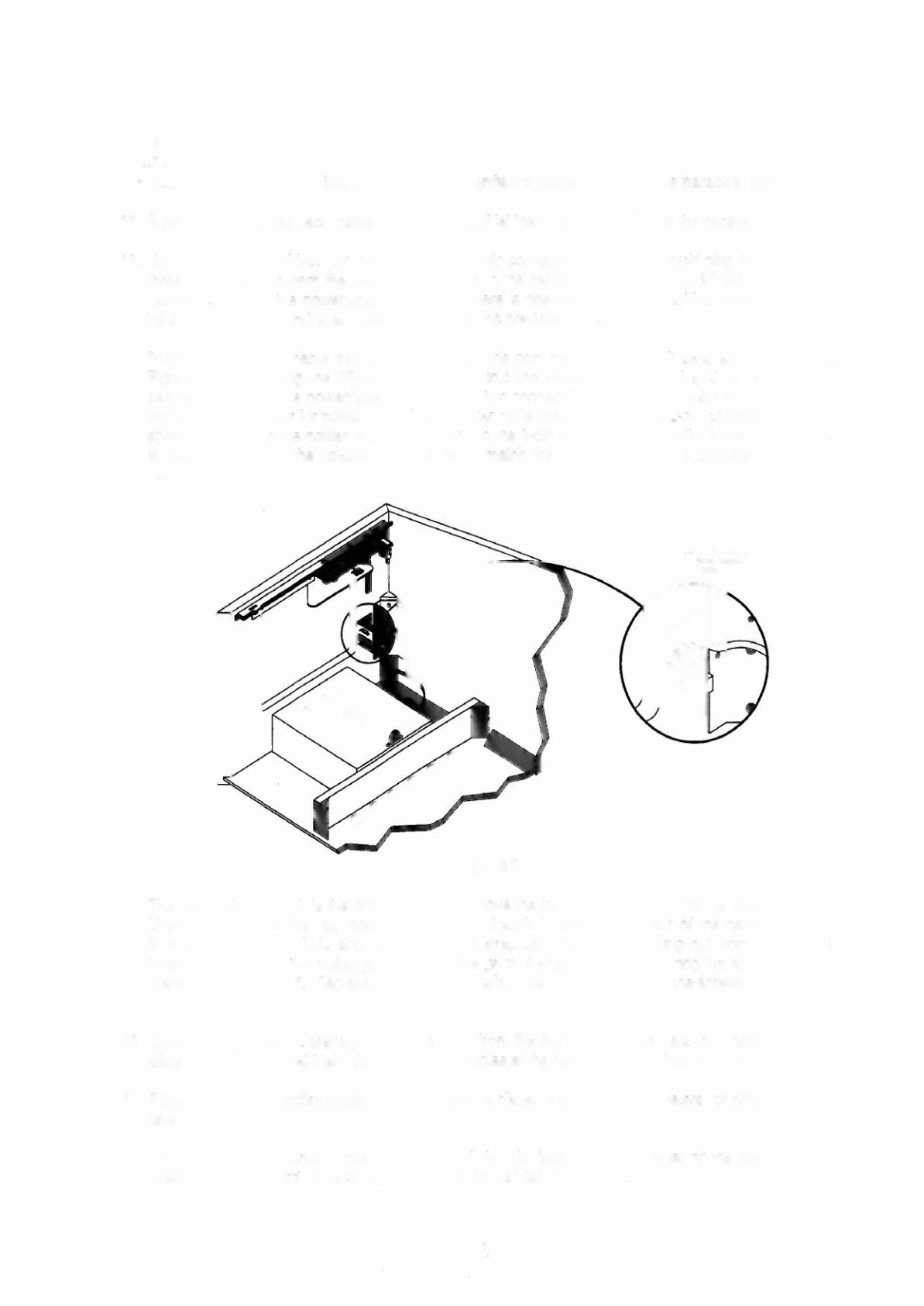
Plug the 9-pin serial cable into the bracket near the coin door and screw it securely in place (see
Figure 9 below). Plug the 25-pin parallel cable into the Power Driver board at J100 and screw it
securely in place. The power/speaker cable has two connectors, a 2-pin connector for the speakers
and a 3-pin connector for power. Plug the speaker cable connector into the 2-pin connector near the
speakers, and plug the power cable connector into the 3-pin isolation tap from the transformer, which
is also located near the speakers. Be sure to match the wire colors on the speaker and power
cables.
Figure 9
The last cable to attach is the ground strap. Remove the four screws holding the backbox rear door.
Unlock and remove the rear door. The ground strap is located in the rear of the cabinet. Reach
through the rectangle hole and pull the ground strap up. Remove the wing nut from the ring lug
located to the left of the rectangle hole. Slip the ground strap loop over the ring lug and secure it in
place with the wing nut. Replace and lock the backbox rear door. Replacing the screws is optional.
13. Open the coin door. Carefully, lift the playfield from the front and tip the back of it onto the slides.
Slide it back into the cabinet. Be sure that the cables at the back of the playfield are not kinked.
14. Place a level or an inclinometer on the playfield surface. Adjust the leg levelers for proper playfield
level (side-to-side).
NOTE: This measurement must be made ON the playfield, not the cabinet or the playfield cover
glass. Tighten the nut on each leg leveler shaft to maintain this setting.
1-5