Basic HTML Version


LAMPS
Yellow (B+)
ffi
Red
~
1
2
3
4
5
6
7
8
Yellow-
Yellow-
Yellow-
Yellow-
Yellow-
Yellow-
Yellow-
Yellow-
Brown
Red
Orange
Black
Green
Blue
Violet
Gray
J137-1
J137-2
J137-3
J137-4
J137-5
J137-{;
J137-7
Jl38-9
w
Q98
Q97
Q96
Q95
Q94
Q93
002
091
Red-
(E)-S-C-A-P-E
Right
5x3,
5x3,
5 x 3,
(R)-E-P-A-I-R
Doctor 4 (W)-H-O
1
Brown
Retum Top
Middle
Bottom
(2 lamps)
J133-1
Left 1
Left 1
Left 1
QOO
11
21
31
41
51
61
71
81
Red-
E-(S)-C-A-P-E
Right
5x 3,
5x3,
5 x 3,
R-(E)-P-A-I-R
Doctor 6 Doctor 3
2
Black
Drain
Top
Middle
Bottom
(2 lamps) (2 lamps)
J133-2
Left 2
Left 2
Left 2
Q89
82
12
22
32
42
52
62
72
Red-
E-S-(C)-A-P-E
Doctor 7 5 x 3,
5x3,
5 x 3,
R-E-(P)-A-I-R
1.5X
W-H-O
Orange
(2 lamps)
Top
Middle
Bottom
1,000,000
3 J133-4
Middle
Middle
Middle
Q88
13
23
33
43
53
63
73
83
Red-
E-S-C-(A)-P-E
ESCAPE 5x 3,
5x3,
5 x 3,
R-E-P-(A)-I-R
2X
W-H-O
4
Yellow
Special
Top
Middle
Bottom
2,000,000
J133-5
Right 2
Right 2 Right 2
Q87
14
24
34
44
54
64
74
84
Red-
E-S-C-A-(P)-E
ESCAPE 5 x3,
5x 3,
5 x3,
R-E-P-A-(I)-R
2.5X
W-H-O
5 Green
3,000,000 Top
Middle
Bottom
Lite Extra
J133-{;
Right 1 Right 1 Right 1
Ball
Q86
15
25
35
45
55
65
75
85
Red-
E-S-C-A-P-(E)
ESCAPE Doctor 2 Transmat
Mini-ply
R-E-P-A-i-(R)
3X
Ball
Blue
2,000,000 (2 lamps)
Award
Left
Transmat
&
6 Jl33-7
Lock
Advance
Q85
Bonus X
16
26
36
46
56
66
76
86
Red-
Left
ESCAPE Hangon Tardis
Mini-ply
Doctor 5 3.5X
Launch
7
Violet
Drain
1,000,000 Score
Right
(2 lamps)
Ball
J133-8
Lock
Q84
17
27
37
47
57
67
77
87
Red-
Left
ESCAPE Video
Doctor 1 Mini-ply
Shoot
4X
Game
8
Gray Retum 500,000
Mode
(2 lamps) Target
Again
Start
J133-9
Q83
18
28
38
48
58
68
78
88
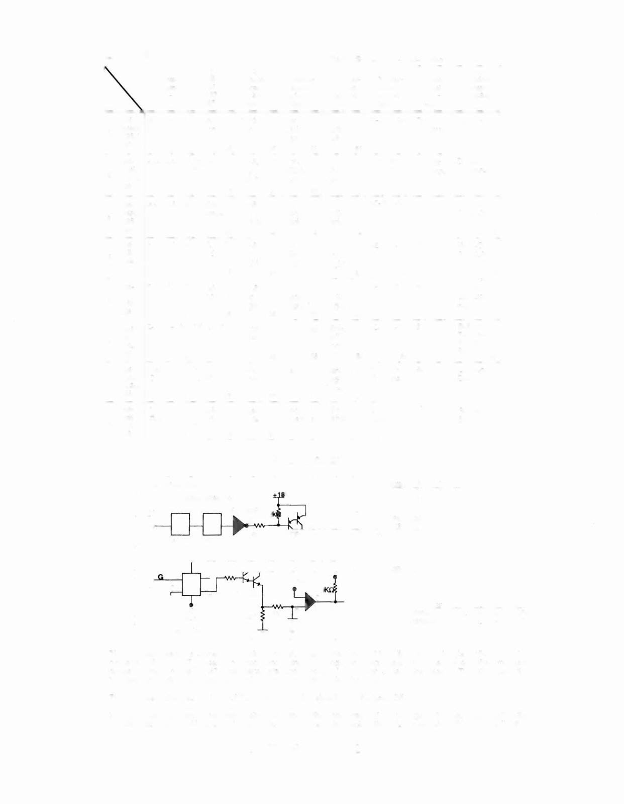
LAMP MATRIX CIRCUIT
r - - - - - - - - - - - - - - - - - - - - - - - - - - - - - -
I
Power Driver Board
Column
I
Red-xxx
,
ROWCIDIEIEI
GI
(normal
H L H L H Off
operation) H L L H L On
Row (example)
The processor sends a signal to the column circuit, causing the output of the UNL-2803 to toggle. When point 'A'
drops low, the TIP107 transistor conducts and point 'B' changes to a high state. At the same time the processor
drives the input of the 74LS74 low, causing a high at output 'F'. A high state at the base of TIP102 causes the
transistor to conduct, bringing the row circuit to ground and tuming the lamp On.
The processor changes the input of the 74LS74 to a high state to tum the lamp Off.
In overcurrent conditions the lamp is shut Off through the comparator. If the voltage at the negative input of the
LM339 rises above 1.4V the output changes to a low, which is fed back to the 74LS74 and shuts the row circuit Off.
DOCTOR WHO 3-2