SEO Version


Flipper Circuit and Lane Change Circuit
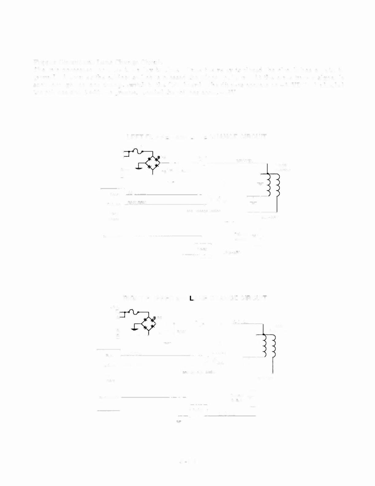
The microprocessor enables the relay to close . Once the relay is closed the circu it has a path to
ground . A soon as the cabinet switc h is pressed the flipper pun s in. At the same time a signal is
sent through the lane change switch to the CPU board. The flippers operate on +50VDC. Unload ed
the coil has about +60Vor greater. Loaded the coilhas about +48V.
LEFT FLIPPER and LANE CHANGE CIRCUIT
1 -I
I
Relay
I
~-~
Row
WHT·RED
GRN"8RN
Column
CPU
Board
J.!1 ) fOCos s or
I-- ----- ----}
RIGHT FLIPPER and LANE CHANGE CIRCUIT
Row
WHT·BRN
GRN·BRN
Column
CPU
Board
~p r oce" " ori"-------------
- -- ,
3-14
Cabinet
Sw~ oh
ORG·VIO
Powered by FlippingBook Publisher