SEO Version


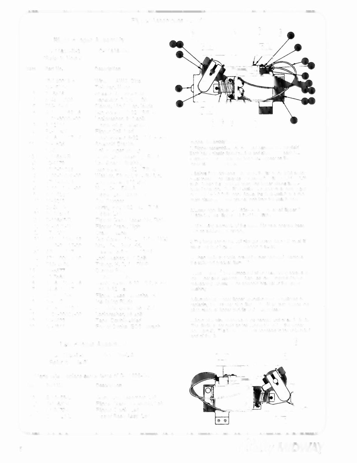

Flipper Assemblies ~cont'd
Right Flipper Assembly
C-11626-R-2
(Refer to Note 3)
Item Part No,
1 HW-30018-6
2 03-7520-2
3 20-6516
4 5045-12098-00
5
RM-21-06
6 401 0-01066-06
7 4701-00004-00
8
A-12111
9 FL-11630
10 4006-01017-04
11 01-7695
'2
10-376
13 8-10S55-R
a)
02-4179
b)
4010-01086-14
c)
4700-00023-00
d)
4701-00004-00
e)
4410-01132-00
f)
A-t065S""
1.) 02-4219
2.) 20-9370-1
3.) 03-8050-1
g)
8-106S7-R
1.) 01-8073-R
2.) 17-1037
3.) 4010-01 066-18
4.) 4410-01127 -00
5.) 4700-00107-00
6.)
4701-00004-00
7.)
RM-23-06
14 23-6577
15 03-7568
16 4006-01005-06
17 4406-01117-00
18 C-11627-R
19 06-14G
20 4105-01019-10
21 4701-00002-00
22 23-6622
23 03-7811
C-11626-R-3
Description
Wire, 18 AWG, Blue
Ty-Wrap, Nylon
Speednut, Tinnerman
Capacitor, 2.2 jlFd, 250V
Sleeve, Vinyl {Cap. leads)
Cap Screw, 10-32
x
3/8,
SH
Lockwasher, #10 split
Flipper Stop Assembly
Flipper Coil (Red)
Mach. Screw, 6-32
x
1/4,
P-RH
Solenoid Bracket
Coil Plunger Spring
Crank Link Assembly, Right
Link Spacer Bushing
Cap Screw, 10-32
x
7/8,
SH
Washer, 5/8 o.d.
x
13164 i.
d.
Lockwasher, #10 split
Nut, 10-32 ESNA
Flipper Link Assembly
Coil Plunger
Spring Pin,
5132
dia.
x
7/16
Flipper Link
Flipper Crank Assembly, Right
Flipper Crank, Right
Crank. Washer
Cap Screw, 10-32
x
H/8,
HCS
Nut, 10-32 Hex Hd.
Washer,
5/8
o.d. x
13/64
i.
d.
Lockwasher, #10 Split
Tubing, H. S. 114DWP
Bumper Plug
Flipper Bushing
Mach. Screw, 6-32
x
3/8,
P-PH
Nut, 6-32 Hex
Flipper Base Assembly, R.
Insulating Blade
Sh. Metal Screw, #5 x
5/8
Lockwasher, #6 splil
Tape, Double-sided
End of Stroke (EGS) Switch
Left Flipper Assembly
C-11626-L-2
(Refer to Note 3)
Item Part No.
(Parts listed replace same items of C-11626-R-3)
Description
13 B-1 0655-l
g)
B-l0657-l
1.) 01-8073·L
18 C-11627-l
Crank link Assembly, left
Flipper Crank Assembly, Left
Flipper Crank, left
Flipper Base Assy, left
Rippel"
AsMmbly
Not ••
1. Flipper assemblies are mounted beneath the playfieki.
Each has a plastic nipper paddle and shaft. And each has
a
flipper rubber. These last two parts appear on the
upper side of the playfleld.
2. Before EOS contacts fully open, the
tip
of the EOS switch
must travel. The distance of trav~ is 0.0150 (+O.otO, -0.0)
inch. 'h'hen the contacts open, the nipper attains its ac-
tuated position.
The
EOS switch contacts must have a gap
01 0.062 ( +
t-
0.015) inch. Adlust the EOS Switch at
a
mini-
mum distance 01 one quarter inch from the switch body.
3.lower righl nipper C-11626-R-2 and lower
ie1I
nipper C·
11626-l-2 use nipper 001 Fl-11629/50V.
<I.AU moving efements clthe assembly must operate freely,
with no evidance of binding.
5.The
large end of the
cea
plunger spring [Item t2) must fit
within It1e four lugs
ot
tbs solenoid bracket.
6.when replacing coils, prevent screw damagel Remove
the SOlenOidbracket (Item 11).
7.Use loctlte™ 242 compound when reattaching sere_to
the flipper stop assembly. Also use this compound when
reattaching screws to the solenoid bracket
Of
tna flipper
bushing.
S.SOmetimes proper nipper operation may be restored
by
replacing the bumper plug (Item
14).
When you replace this
plug, readlust flipper paddle and
shalt
position.
9.Solid blue wire connects to the banded end
of
each diOde.
The diOde is mounted on the connector end of the flipper
coil [Item 9). me trace cotor wife connects to the unbanded
end
of
the diode.
I I
13
@a!fy/MIDWAY
Powered by FlippingBook Publisher