Basic HTML Version


CPU L.E.D.'s
The CPU has three L.E.O.'s located on the upper left side of the board: 019, 020, and 021. On
game power-up 019 and 021 turn on for a moment then, 019 turns off and 020 starts to blink
rapidly. 021 remains on. The system has detected a problem if the following happens:
CPU Board L.E.D. Error Codes
Center L.E.O. blinks one time
ROM Error U6
Center L.E.O. blinks two times
RAM Error US
Center L.E.O. blinks three times
Custom Chip Failure U9
Sound Board Beep Error Codes
Upon Game Turn-On:
1 Beep
=
Sound Board OK
2 Beeps
=
U2 Failure
3 Beeps
=
U3 Failure
4 Beeps
=
U4 Failure
S Beeps
=
US Failure
6 Beeps
=
U6 Failure
7 Beeps
=
U7 Failure
8 Beeps
=
US Failure
9 Beeps
=
U9 Failure
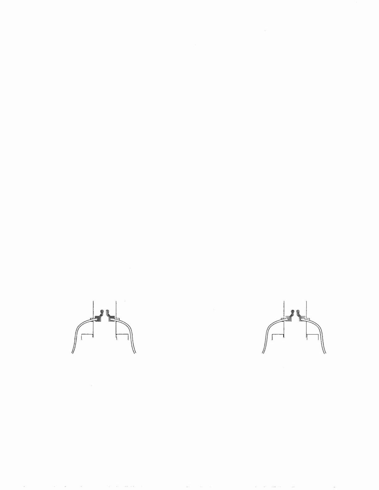
OPTOTHEORY
The opto receiver {Photo Transistor} should be approximately 0.1-0.7 volts when the opto beam
is unblocked and approximately 11-13 volts when the opto beam is blocked. The opto transmitter
{L.E.O.} should always be approximately 1.4 volts. Note, the transmitter {L.E.O.} is larger than
the receiver {Photo Transistor}; it protrudes further from its case.
LED Board (A-16908)
Transmitter
1.0-1 .1 Volts
Photo Transistor Board (A-16909)
Receiver
0.1-0.7V Unblocked
11 -13V Blocked
Infrared Ray
Green
o
WHT
Gray-XXX
Black
Gray-Yellow
Orange-XXX
1-50