Basic HTML Version


TEST/DIAGNOSTIC PROCEDURES
(Continued)
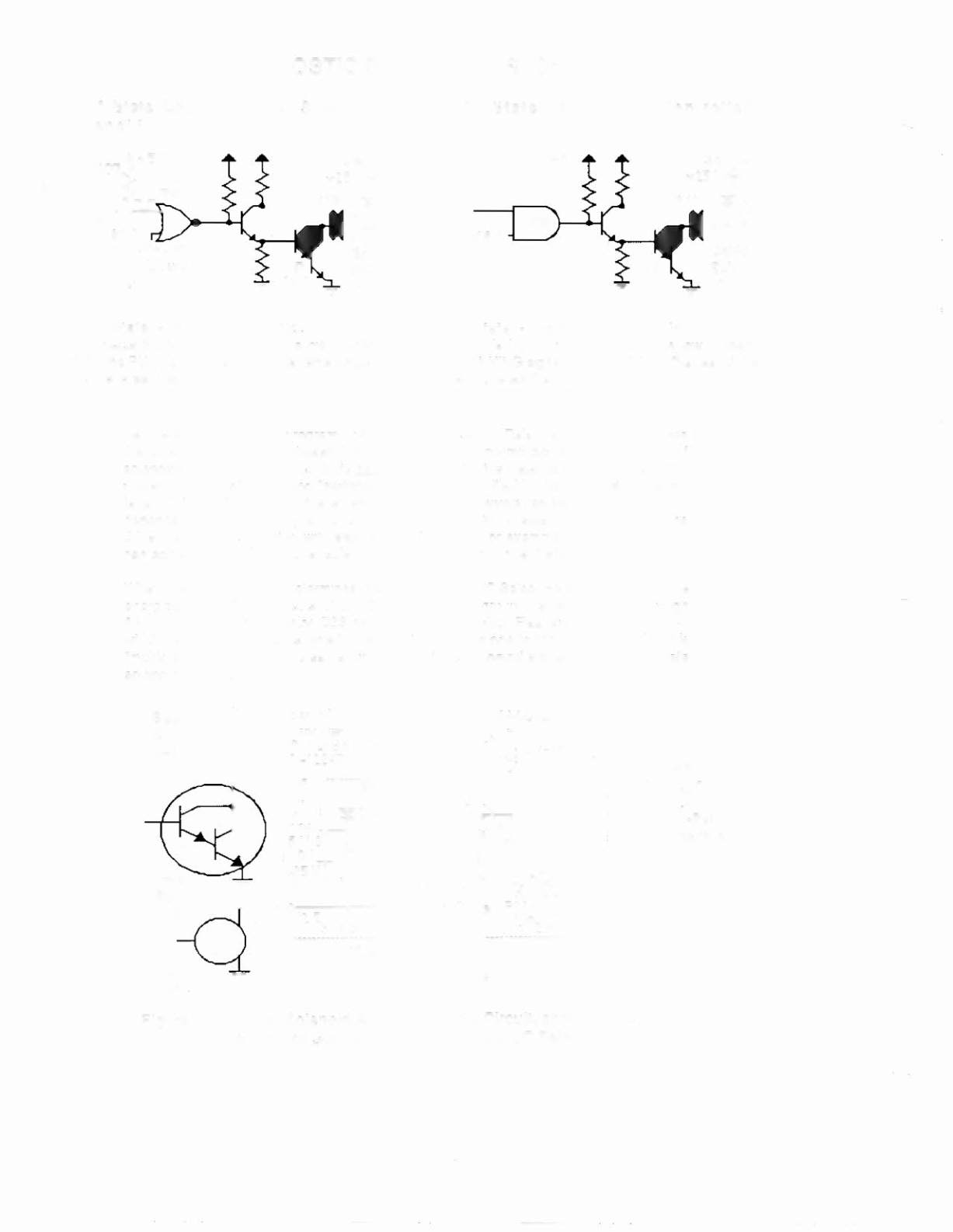
"On" State Logic - Special Solenoid
Solenoid
Sol. B+
+25V~
lP19
BJl3
Special
Sol.
"ON"
"Off" State - Special
Soleno id:
The Special Switch Trigger Input goes low. Mean-
while, the PIA line remains high. The remaining sig-
nals reverse their states.
"On"
State Log Ie
Controlled
Sol. B+
IP::S~
Cntl1d
Sol.
"ON"
"Off" State - Controlled Solenoid:
The Enable Input (from the PIA) goes low. Mean-
the BLANKING signal remains high.
The rest of the
signals reverse their states.
NOTE
As directed by the game program, the Solenoid AlC Select Relay (solenoid 12) switches
the solenoid B+ power between two power busses to permit actuating two groups of
solenoids at the proper times. In its de-energized state, the Relay connects the 'circuit A
power' to 16 "controlled" and "switched" solenoids (identified in the table with no suffix
letter or the letter A, after the solenoid number).
Ind ividual solenoid operation then
depends on the game program enabling the ground path for solenoid actuation via the
driver transistor associated with each solenoid circuit. For example, the game program
can actuate the Outhole Kicker solenoid (sol. 01A), via the driver transistor
033.
When the game program determines that the Solenoid AlC Select Relay (sol. 12) must be
energized, the relay connects 'circuit C power' to eig ht group C solenoids (01 C through
OBC). Now, driver transistor Q33 can actuate the Pin-Bot Flashers circuit (sol.
0'
C),
which has two lamp circuits, one to the Insert Board and one to the playlield.
Using this
"multiplexing" technique, the same driver transistor can control actuation of
two
separate
solenoid circuits.
System l1B-~',
CPU Board
I
0-11883
Sol.
OlC
Orn
Pin·Bot
Flashers
Figure 4. Typical Solenoid
AIC
Select Relay Circuit, showing the
function of Solenoid 12, the Solenoid
Ale
Select Relay.
TAXI 30
_
....•
_-
..
_ - --
.